Type "ODTS 2"type odts1

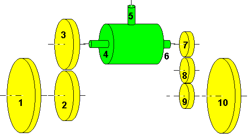
Started by some discussions with Ian White, I set out to design some chariots around ready made differentials. The most elementary design is shown here, comprising merely on differential (the green blob; in its former life the power shaft was connected to rod 5, while the car wheels attached to 4 and 6) and two sets of gears to connect to the road wheels. Note that the left set reverses the sense of rotation while the right set doesn't, but both sets cover the same distance from differential to main axle.
Some notes about car differentials: As we use it the wrong way round by driving the former power feed, worm wheel types can not be used. Next stumbling block may be the sense of rotation: make sure, that the pointer rotates the right way round. If not, simply swap the gear sets (or in other words, mirror the design) but keep the differentials orientation. Finally, we need the reduction factor of the differential on hand. In my equations, the symbol k denotes the inverse of the number of revolutions (no need to be an integer number !) of shaft 5, when shafts 4 is rotated exactly once while shaft 6 is held stationary. For a "pretty" chariot, aim for a k of about 2 (may require to add more gears).

As usual, the dimensioning equations:
 
(a:) rot4 + rot6 - k * rot5 = 0
(b:) n2 * rot2 + n3 * rot3 = 0
(c:) n7 * rot7 + n8 * rot8 = 0
(d:) n8 * rot8 + n9 * rot9 = 0
 The remaining constraints:
(e:) rot1 = rot2
(f:) rot3 = rot4
(g:) rot6 = rot7
(h:) rot9 = rot10
Composition
(b,e,f=>) rot4 =  - (n2 / n3) * rot1
(c,d,g,h=>) rot6 =  (n9 / n7) * rot10
(a=>i:) k * rot5 = (n9 / n7) * rot10 - (n2 / n3) * rot
To make it "south-pointing" requires, that if rot1 is held 0, rot5 has to be exactly one turn when wheel 10 of diameter d10 covered one full circle (centre at wheel 1's contact to the ground, radius equal to track width t):
(j:) d10 * rot10 * PI = 2 * t * PI   d1 * rot1 * PI = 2 * t * PI
(k:) rot1 = 0 rot10 = 0
(l:) rot5 = 1 rot5 = -1
(i=>) rot10 = k * (n7 / n9) rot1 = k * (n3 / n2)
(j=>) d10 = 2 * t / rot10 d1 = 2 * t / rot1
The same method can be applied to calculate the required size for wheel 1, see rightmost column of table above.

Given Parameters (Your choice !)

Reference
Size Description
2
n2[teeth] Spur gear, fixed to wheel 1
3
n3[teeth] Spur gear, fixed to left differential shaft
7
n7[teeth] Spur gear, fixed to right differential shaft
8
n8[teeth] Spur gear, Idler
9
n9[teeth] Spur gear, fixed to wheel 10
k
k =  Differential reduction factor
T
t = [length units] Track width

Derived Parameters

Reference
Size Description
1
d1[units of t] Road wheel, free running on axle
10
d10[units of t] Road wheel, free running on axle

© odts 2002