 |
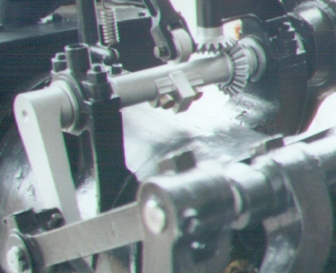
Flywheel Crank
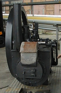
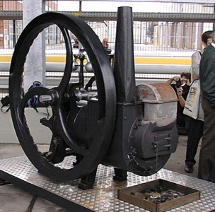
The flywheel is dynamically balanced, see partially filled rim in
the picture to the left. In the static (stopped) state there is a considerable
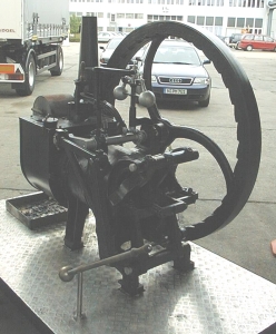
imbalance, which is used to start the engine: Pumping the lever to the
right of the engine, the wheel can be turned easily to the upper dead center,
where the maximum heat is stored inside the displacer piston. From there
on the gravity turns the engine through half a cycle, up the point where
the heat meanwhile stored in the displacer is passed back to the new load
of air.
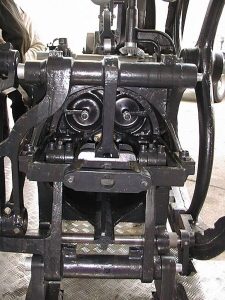
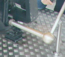 Crank
Lever Crank
Lever
|
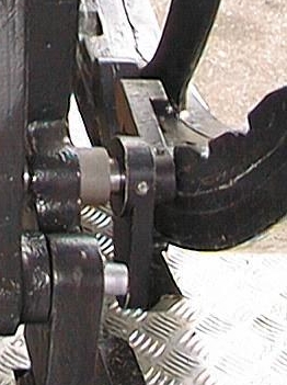
Crank Ratchet |

Ratchet teeth on flywheel |
